
Understanding Coil Circuitry
Think about this! Finned-tube heat exchanger coils have no movable parts, yet they are the most misunderstood principal component in an HVAC system. That statement becomes true because a coil has a changing performance based on what’s fed on both the liquid and air side. If you change the data that creates a rating on a coil, the coil’s output and performance changes. It’s that simple.
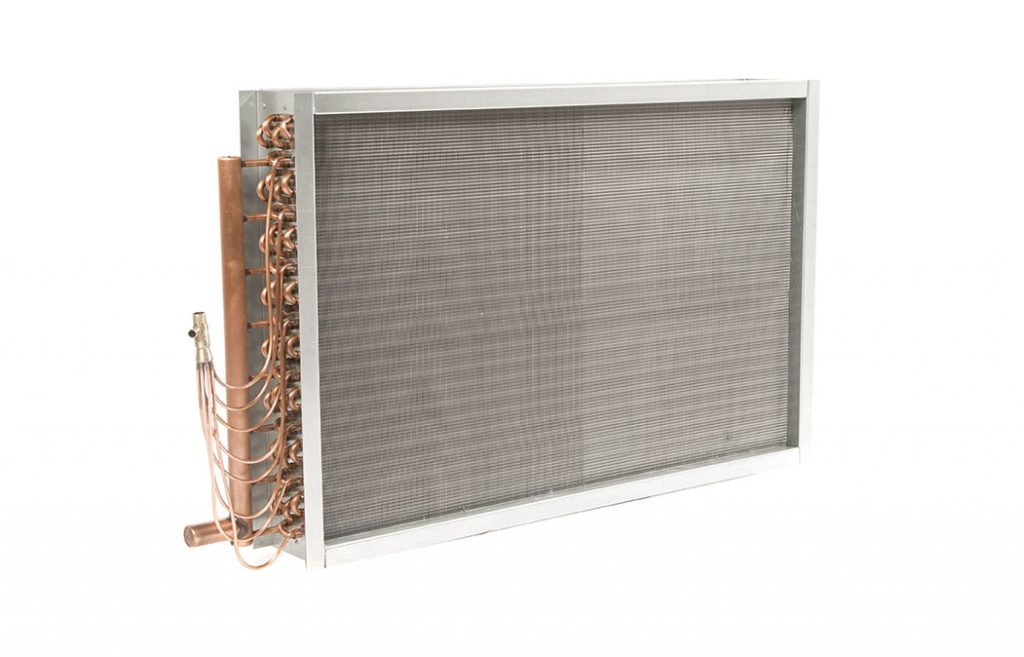
Example: Consider a “10 ton” chilled water coil that is 4 rows, 8 fins per inch, 5/8” OD tubes, 24” finned height x 48” finned length. 10 tons equals 120,000 BTUH and based on 4000 CFM of air from 80/67 entering air and 45 degrees entering water and 24 GPM. The circuitry is half circuit-8 pass type. The water velocity is 3.33 feet per second (FPS). The water pressure drop is 9.8 feet. If we change the 4000 CFM to 3000 CFM, the BTUH would drop and so would the air resistance.
Circuitry has a lot to do with coil capacity and fluid side pressure drop. Coils are circuited to meet the BTUH requirement of an application while keeping the fluid side pressure drop under the requirements on the fluid side of the distribution system.
In the above example, we have 24 GPM of water in the application. If the coil is 24” high with 5/8” OD tubes, each row will be 16 tubes high. If you have 4 rows of 16 tubes, each coil will have 64 total tubes. The term “half circuit–8 pass” means that if there are 16 tubes in each row, we will feed 24 GPM of water through 8 tubes (half of 16). If there are 64 tubes in the coil, divide 64 tubes by 8 tubes being fed indicates an 8-pass coil.
Envisioning this is easy. The supply header would have 8 tubes connected to the back side of the manifold, and those 8 tubes would carry 24 GPM of water down to the other end of the coil. Since the coil is 16 tubes high, and you would use 8 of them in row number 1, and you would have return bends sending that same 24 GPM back to the connection end. You now have two passes on row 1, and it would be the same for rows 2, 3 and 4. That’s 4 rows and the 24 GPM would make 8 passes through the coil.
If I used “full circuit” in this example, we would feed 16 tubes instead of 8 tubes and make 4 passes, because each row would be used for each pass. Again, 64 tubes and 16 feeds equal 4 passes.
Rule #1 – If you count the number of stacked tubes in any coil and count the number of tubes connected to the supply header, you will have the information to create the circuitry of the coil – except condenser coils.
Why does circuitry matter? It matters because circuitry deals with velocity of gas/fluid inside the tubes. The higher the velocity, the more BTUH heat exchanged. That’s a good thing. However, the faster the velocity, the higher the fluid pressure drop. Both requirements are designed by the engineer, and a coil manufacturer must select the circuitry that meets both criteria. Today’s computers select the coil circuitry for you. If Southwest Coil is replacing a coil, we must match what is existing.
There are times when we will change the circuitry of a coil and even the rows in the direction of air flow based on discussions with the owner or his agent. A coil/unit at the end of a chilled water loop may not receive the expected GPM of its original design. Therefore, the BTUH would be underperforming. Sometimes a change in circuitry will speed up the GPM that’s being delivered to increase the new coil’s performance.
DX COOLING COILS
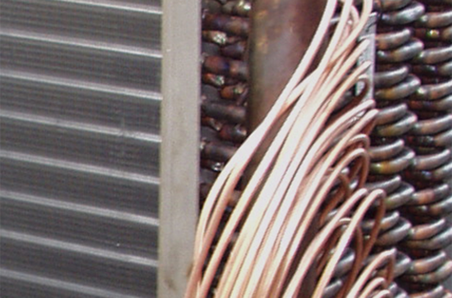
DX evaporator coils have circuitry as well. The “spaghetti leads” you see coming from a distributor are the same as feeds behind a header on a chilled water coil. The liquid fills the distributor and that liquid is distributed down each lead proportionally. This creates a refrigerant fluid velocity that creates good and efficient heat transfer while having a pressure drop that is satisfactory for the compressor to pump the refrigerant through the system. When replacing a DX coil, getting the tonnage of a system, refrigerant type, and suction temperature is all you will need. Getting the model number of the condensing unit or the rooftop unit that’s hooked up to the DX coil can also help. If none of this information is available, expansion valve and distributor model and number and counting distributor leads into the coil may be required.
CONDENSER COILS
Condenser coil circuitry has 2 other criteria that other coils do not. 1) The refrigerant goes in as a gas and turns to liquid before it gets to the return end. The refrigerant in a hot gas state takes up more area than in a liquid state. A condenser coil then has liquid sub cooling to cool down the refrigerant further. 2) There can be 3 or even 4 headers per circuit on a condenser coil. These headers and feed have a rhyme and a reason. Our advanced computer programs can select these for you.

When replacing a condenser coil, the following points are very important and save time and money:
- Count the number of tubes connected to each header
- Know the header OD and the connection size
- Take well lighted pictures showing the circuity – pictures are worth a thousand words!
- Find out the make and model number (from decades of experience building condenser coil sets, we know the importance of knowing the make and model #).
Rule #2 – With DX or condenser coil replacement, be sure to follow the above guidelines.
Southwest Coil exclusively represents USA Coil & Air in the southwest region, and we understand coil circuitry for all types of coils and know the importance of making informed decisions when replacing coils. We have withstood the test of time with 4+ decades of experience in the HVAC industry.
Contact the experts at Southwest Coil for all your coils needs!
We’re the best in the business – take advantage of our knowledge and experience.