
How to Achieve Coil Capacity
A heat exchanger, and in the following example a finned tube coil, can only meet its intended performance capacity if the air side and fluid side parameters are “as specified”. The specified parameters for all coils are selected to meet or exceed the intended capacity. If the parameters are changed, the capacity will also change.
How a coil works:
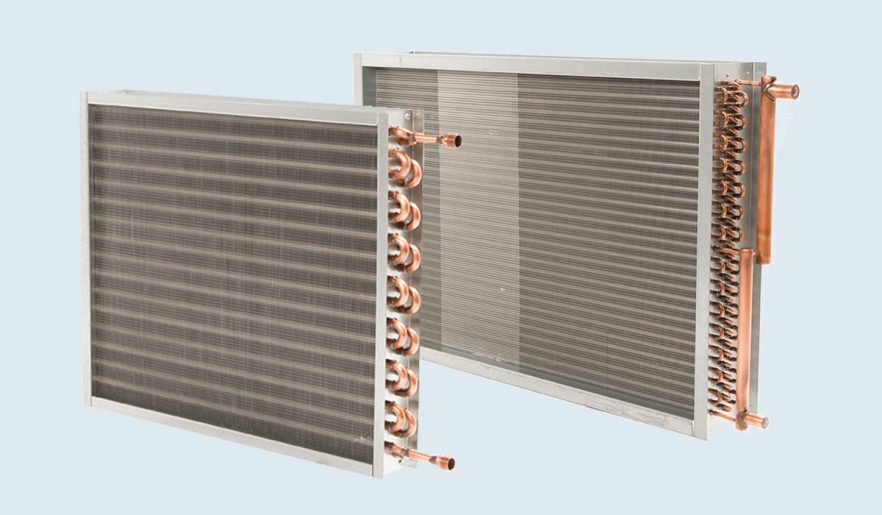
Coils have two distinct sides. One is the air side and the other is the fluid side. On the air side, air travels through and across fins that act as secondary heat exchangers and also create a better air path for distribution across the tubes. The tubes are known as the primary surface.
This air has a quantity in any given selection and is normally in CFM of air. The face area of the coil is selected to create a desired air velocity across the finned tubes. In heating or dry cooling, these velocities can be as high as 1,000 FPM. With dehumidifying coils, the velocity can’t be selected higher than 550 FPM. Why? When you increase the velocity, there is a chance that the water forming on the finned tube surface will be taken downstream and into fans or even down ductwork. This phenomenon is called “water carryover”. Feet Per Minute is fast – 500 FPM is 5.7 miles per hour.
The fluid side of the finned-tube coil normally has a header that is sometimes known as a manifold. This is where the fluid enters the coil. With a refrigerant coil, the manifold is replaced by a distributor with distributor leads out to the tubes in the coil. In any water or refrigerant coil (even a steam coil), the number of tubes connected to the header (manifold) is based on a calculated velocity of fluid. This velocity is based on the required amount of fluid and takes into consideration optimum heat transfer and also allowed fluid resistance. Fluid resistance comes into play because there must be a pumping means to be sized that distributes through the entire coil from its inlet to outlet.
Examples:
Heat 10,000 CFM of air from 60 degrees F. to 90 degrees F. using water that enters at 180 degrees F. and leaves at 160 degrees F. In this example, it’s 325,500 BTUH. The GPM would be 32.55 (GPM = BTUH divided by 20-degree water TD x 500). It was specified that the coil would be 36” finned height x 72” finned length which is 18 square feet (10,000 CFM divided by 18 square feet equals 555 FPM air velocity). When inserted into our computer program, this coil will be a 5/8” OD tube coil, 1 row and 10 fins per inch and 36” finned height x 72” finned length.
Changing the parameters examples below:
- If the CFM is changed from 10,000 CFM to 11,000 CFM, the air velocity and the BTUH will both go up, but the air temperature rise will go down. The air resistance will also go up (more air into the same coil face size).
- If the entering air is changed from 60 degrees F. to 40 degrees F. the BTUH and the air temperature difference will increase, but the leaving air temperature will go down. The water side will have a wider water temperature difference.
- If the water entering temperature is changed from 180 Degrees F. to 160 degrees F. , the air temperature will rise. The leaving air temperature will go down.
- If the GPM of water is reduced from 32.55 GPM and to 25 GPM, the air rise will go down and the water temperature difference will be wider. Overall, the BTUH of the coil will be reduced. Less GPM equals less water pressure drop.
Many coils installed today do not have the selected parameters feeding the coil to achieve the specified capacity – too much or too little air or water temperature differences and water quantity not as specified). A coil has no movable parts and can only achieve its intended capacity based on what you feed it. IMPORTANT: This doesn’t include fouling of coils over time which also negatively affects the coils intended capacity.
Southwest Coil represents USA Coil & Air exclusively in the Southwestern Region. Together, we have been in this business for 4+ decades, and we have seen it all, including many coils that have been “starved” for air or fluid and fouled to the point that the intended capacity is impossible to meet. We can help you with a replacement coil and/or design a new coil based on your actual jobsite. REMEMBER: We build replacement coils for any manufacturer’s design and can usually ship in 4 weeks or provide one of our expedited schedules for those urgent coil situations.